March 1, 2026
Pipe Bending Tolerances Explained: What Engineers Need to Know
Team Pipe Processing
In fabrication and manufacturing, precision is everything. When bending pipes for automotive, HVAC, construction, or industrial applications, even the smallest deviation can affect performance, safety, and long-term reliability. That’s why pipe bending tolerances—the allowable variation from design specifications—are so important.
This guide explains what pipe bending tolerances are, why they matter, and how engineers can manage them for successful projects.
What Are Pipe Bending Tolerances?
Pipe bending tolerance![]()
![]() refers to the acceptable limits of deviation from the intended bend angle, radius, or alignment. No bend is 100% perfect—machines, materials, and processes introduce slight variations. Tolerances define how much variation is permissible without compromising function or safety.
refers to the acceptable limits of deviation from the intended bend angle, radius, or alignment. No bend is 100% perfect—machines, materials, and processes introduce slight variations. Tolerances define how much variation is permissible without compromising function or safety.
For example:
- A 90° bend with ±1° tolerance means the bend can range from 89° to 91°.
- A centerline radius with ±1 mm tolerance means the bend can be slightly tighter or wider but still within specification.
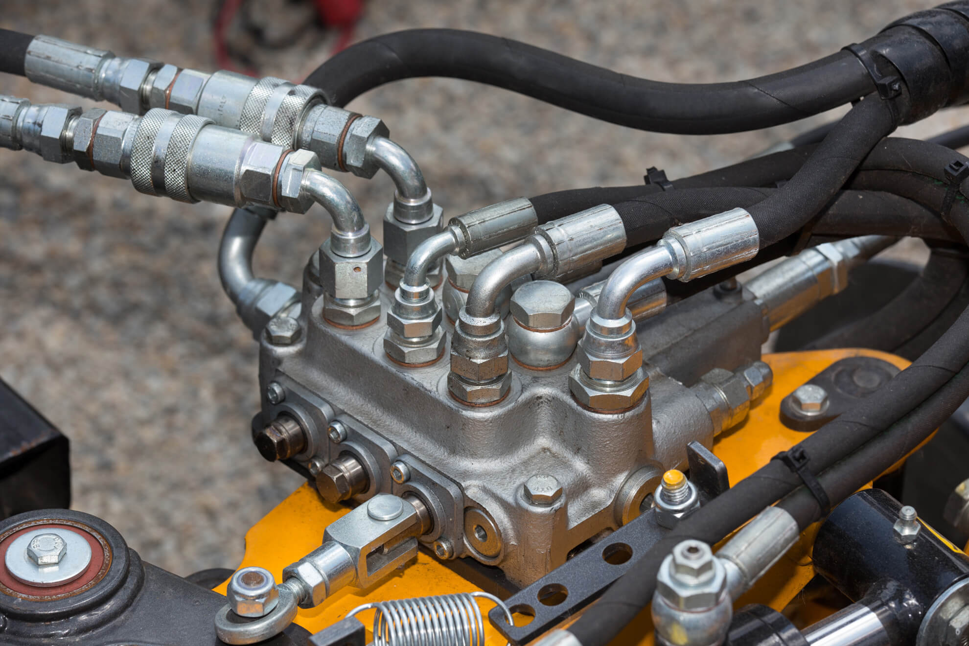
Key Tolerances in Pipe Bending
- Bend Angle Tolerance – The allowable deviation in the pipe’s angle after bending.
- Bend Radius Tolerance – The acceptable difference between the designed and actual radius.
- Wall Thickness Variation – Changes in pipe wall thickness due to stretching or compression during bending.
- Ovality (Roundness) – Pipes may become slightly oval during bending; tolerances define how much deformation is acceptable.
- Twist and Alignment – Pipes must stay aligned to avoid assembly issues in multi-component systems.
Why Pipe Bending Tolerances Matter
- Structural Integrity: Excessive deviation can weaken the pipe and create stress points.
- Assembly Fit: Tight tolerances ensure bent pipes fit seamlessly into complex assemblies.
- Performance Reliability: Precise bends improve fluid flow, pressure control, and load-bearing capacity.
- Cost Efficiency: Staying within tolerance reduces rework, scrap, and downtime.
- Compliance: Many industries have strict standards that demand adherence to tolerances.
Common Tolerance Ranges in Pipe Bending
| Tolerance Type | Typical Range | Impact if Exceeded |
|---|---|---|
| Bend Angle | ±0.5° to ±2° | Misalignment in assemblies |
| Bend Radius | ±0.5 mm to ±2 mm | Poor fit and increased stress |
| Wall Thickness | ±10% variation | Weak spots, risk of leaks or failures |
| Ovality | Up to 8% of diameter | Reduced flow efficiency, poor fit |
| Alignment/Twist | ±1 mm to ±3 mm | Assembly difficulties, stress on joints |
*Ranges may vary depending on material, pipe size, and bending method.
Industry Standards & Specifications Engineers Should Reference
Pipe bending tolerances are rarely defined by a single standard. Instead, they sit at the intersection of design codes, material standards, and fabrication practice. Understanding what each standard does — and does not — cover is critical.
ASME (B31 Series & Section IX)
ASME B31 codes (B31.1, B31.3, B31.4, etc.) govern piping system design, not fabrication precision.
These codes focus on:
- Allowable stress
- Minimum wall thickness
- Pressure and temperature limits
They do not explicitly define bend angle tolerance, ovality limits, or dimensional accuracy for fabricated bends.
ASME Section IX applies when bending is part of a qualified welding or forming procedure, particularly in pressure systems. It addresses:
- Procedure qualification
- Material behavior during forming
- Mechanical property retention
confusion: Engineers often assume ASME defines dimensional tolerances — it doesn’t. Those must be specified separately.
ASTM: Material-Driven Tolerance Implications
ASTM standards define material properties, not bending accuracy.
ASTM specifications control:
- Chemical composition
- Mechanical strength
- Heat treatment condition
These properties directly affect:
- Springback behavior
- Wall thinning during bending
- Achievable minimum CLR
Different ASTM grades of the same material can behave very differently during bending, making material selection a tolerance-critical decision.
ISO / EN Bending Tolerance References
ISO and EN standards are more explicit about forming tolerances, particularly in structural and architectural applications.
Examples include:
- ISO dimensional tolerance frameworks
- EN standards for hollow sections and formed components
These standards often define:
- Permissible angular deviation
- Ovality limits
- Straightness and roundness requirements
They are commonly used as reference baselines, even when projects are governed by ASME or ASTM.
Client-Driven vs Code-Driven Tolerances
In practice, most pipe bending tolerances are:
- Client-specified
- Project-specific
- Application-driven
Codes ensure safety. Clients define fit, alignment, and performance expectations.
Best practice: Clearly separate code compliance from fabrication tolerance requirements on drawings and specifications.
What Standards Do Not Define (Critical Clarification)
Most standards do not specify:
- Bend angle tolerance (±°)
- Ovality percentage after bending
- Acceptable wall thinning
- End-to-end dimensional accuracy
These must be agreed upon between engineer and fabricator — ideally before production.
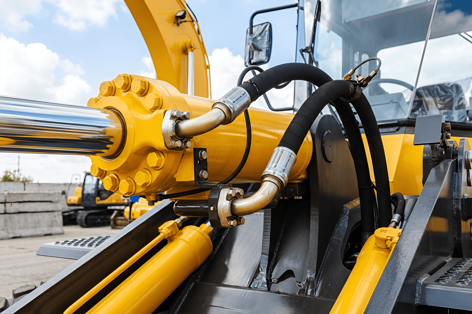
How Bending Methods Affect Achievable Tolerances
Bending tolerances are not just a design decision — they are a process outcome. Selecting the wrong bending method is one of the fastest ways to miss tolerance targets.
Rotary Draw Bending
Rotary draw bending delivers the tightest and most repeatable tolerances.
Excellent control of:
- Bend angle
- Centerline radius (CLR)
- End location
Ideal for:
- Small CLR
- Thin-wall pipes
- Multi-bend components
This method is commonly used where precision fit-up and assembly accuracy are critical.
Mandrel vs Non-Mandrel Bending
Mandrel Bending
Internal mandrel supports the pipe during bending
Minimizes:
- Ovality
- Wrinkling
- Excessive wall thinning
Enables tighter tolerances, especially on thin walls
Non-Mandrel Bending
Lower tooling and setup cost
Greater risk of:
- Out-of-roundness
- Wall thinning
- Acceptable where tolerances are relaxed
This is a classic cost vs tolerance trade-off decision.
Roll Bending
Roll bending is optimized for large-radius bends, not precision geometry.
Suitable for:
- Structural components
- Architectural applications
- Large CLR requirements
Limitations:
- Less accurate angle control
- Larger dimensional variation
- Not ideal for tight fit-up assemblies
Tolerance expectations should be intentionally looser when roll bending is selected.
Induction Bending
Induction bending uses localized heating, which introduces thermal variables.
Advantages:
- Very large diameters
- Thick-wall pipes
- Tight CLR on heavy sections
Challenges:
- Thermal expansion and contraction
- Increased dimensional variability
- Material property changes
Post-bend correction and machining allowances are often required to meet final tolerances.
Material-Specific Tolerance Considerations
Machines bend pipes — but materials decide how accurately they bend.
Carbon Steel vs Stainless Steel
Carbon steel:
- Predictable behavior
- Moderate springback
Stainless steel:
- Higher springback
- Greater force required
- Tighter process control needed
Aluminum & Springback Challenges
Aluminum exhibits significant elastic recovery
Requires:
- Over-bending compensation
- Careful tooling selection
Tight tolerances are achievable, but less forgiving than steel
Duplex & High-Strength Alloys
Higher yield strength increases:
- Springback
- Ovality risk
- Mandrel use and process control become essential
- Tolerances often need adjustment at the design stage
Thin-Wall vs Thick-Wall Pipes
Thin-wall:
- More sensitive to ovality and wrinkling
- Requires mandrel support
Thick-wall:
- Better dimensional stability
- Higher forming forces
- Tooling precision becomes critical
How Engineers Can Manage Pipe Bending Tolerances
- Select the Right Bending Method – Mandrel and rotary draw bending achieve tighter tolerances than roll or compression bending.
- Choose Quality Materials – Consistent material properties reduce variations.
- Leverage CNC Bending Machines – Automation ensures repeatability and precision.
- Design with Tolerance in Mind – Allow reasonable tolerance limits in your design phase.
- Inspect and Test – Use calipers, laser scanners, or non-destructive testing (NDT) to verify tolerances.
Conclusion
Pipe bending tolerances are not just technical details—they are critical factors that determine structural integrity, assembly fit, and overall performance. By understanding and controlling tolerances, engineers can design and fabricate piping systems that are safe, reliable, and cost-effective.
Modern bending technologies, combined with the right material choices and quality control measures, make it possible to achieve precise results every time.
Share it!
Discuss Pipe Bending, Fabrication Project & Possibilities
From technical questions to custom fabrication needs, we’re here to help. Whether you’re exploring materials, need support with FRP or R&D, or just have feedback—reach out and start the conversation.